Laser Manufacturing Processes
The Complete Engineering Guide to Cutting, Welding, Drilling, Heat Treatment, Cladding, and Marking...

A Focused Beam Changed Everything She Knew About Precision
Elena Vasquez had a problem that was costing her fabrication shop a fortune.
Every quarter, her team scrapped thousands of units of value in ruined parts. Warped heat-affected zones from plasma cutting. Brittle welds from arc processes that dumped too much thermal energy into thin-gauge stainless. Drill holes in turbine components that were so inconsistent, her rejection rate had climbed above 18 percent.
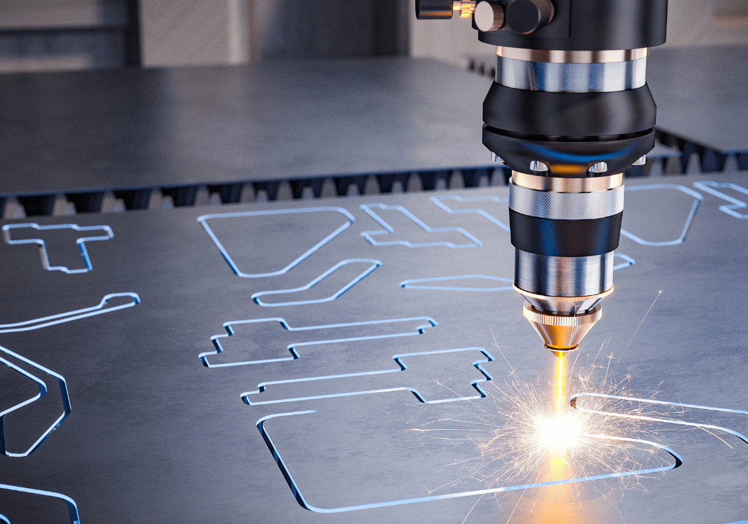
Then she watched a demonstration of an industrial laser cut through 6 mm mild steel like a hot wire through wax — clean edges, minimal kerf, heat-affected zone measured in fractions of a millimeter.
That was the moment she realized: the laser isn't just another tool. It's a fundamentally different way of delivering energy to a workpiece.
What follows is everything you need to understand about laser manufacturing processes — from the physics of beam generation to the specific cutting speeds, welding parameters, drilling methods, heat treatment variables, cladding techniques, and marking technologies that make lasers one of the most versatile tools in modern manufacturing.
What a Laser Actually Is (And Why It Matters for Manufacturing)
The word LASER stands for Light Amplification by Stimulated Emission of Radiation. At its core, a laser is a unit that produces optical-frequency radiation in intense, controllable quantities of energy. When directed against the surface of a material, this energy is high enough to cause a localized effect — heating, melting, or vaporizing — while leaving the surrounding material virtually untouched.
That localized control is the key advantage. Heating by a laser is controlled to produce only the desired result in a specific area, ensuring low part distortion.
The Four Basic Components of Every Industrial Laser
Every laser, regardless of type, contains four fundamental components:
- An amplifying medium — the material that generates laser light (solid crystal or gas mixture)
- An excitation source — the energy input that stimulates the medium (flashlamps or electrical discharge)
- An optical resonator — mirrors arranged to amplify light by bouncing photons back and forth along the optical axis
- An output transmission device — the mechanism that allows the amplified beam energy to exit the laser
┌──────────────────────────────────────────────────┐
│              BASIC LASER COMPONENTS               │
│                                                   │
│  ┌─────────┐    ┌──────────────┐    ┌─────────┐  │
│  │  100%    │    │   Active     │    │Partially│  │
│  │Reflective│◄──►│   Laser     │◄──►│Transmis-│──── Laser Beam
│  │  Mirror  │    │   Medium    │    │  sive   │  │    Output
│  └─────────┘    └──────────────┘    │ Mirror  │  │
│                        ▲             └─────────┘  │
│                        │                          │
│                 Excitation Energy                  │
│              (Flashlamps or Discharge)             │
└──────────────────────────────────────────────────┘
The Two Dominant Industrial Laser Types
Solid-State Lasers (Nd:YAG)
The amplifying medium is a solid crystal of optically pure material — typically yttrium aluminum garnet (YAG) doped with neodymium (Nd). A burst of light from flashlamps arranged in a reflective cavity concentrates excitation energy into the crystal. Neodymium lasers emit radiation at 1.06 µm (near infrared).
Carbon Dioxide (CO₂) Lasers
The amplifying medium is a gaseous mixture of helium, nitrogen, and carbon dioxide. Gas molecules are energized by an electric discharge between strategically placed cathodes and anodes. CO₂ lasers produce light at approximately 10.6 µm wavelength.
That tenfold difference in wavelength between these two laser types fundamentally determines which applications each is best suited for.
Laser Light: Why It's Different from Every Other Energy Source
The transmitted laser light beam has three characteristics that set it apart from every other energy source in manufacturing:
- Monochromatic — one color, one specific wavelength determined by the laser medium
- Coherent — parallel rays with low divergence and high brightness
- High energy density — coherent laser light can be 100,000 times higher in energy density than equivalent-power incoherent light
The most important aspect of coherent light for industrial applications is directionality, which reduces dispersion of energy as the beam travels over comparatively long distances to the workpiece.
Beam Divergence and Brightness
The slight tendency of a laser beam to expand in diameter as it moves from its source is called beam divergence. This value is critical because it determines the size of the focused spot on the work surface.
The beam-divergence angle for high-power industrial lasers is larger than the theoretical diffraction-limited value because divergence tends to increase with increasing laser output power.
Brightness — the power emitted per unit area per unit solid angle — is a major characteristic of solid-state lasers. Because the laser produces very high levels of power in very narrowly collimated beams, it's a source of exceptionally high brightness energy.
A beam-quality factor, M², is commonly used to define productive performance. This factor measures the ratio between the spot diameter of a given laser to that of a theoretically perfect beam. Beam quality is expressed as "times diffraction" and is always greater than 1.
Beam Focusing: Where Physics Meets Precision
The diameter of a focused laser beam spot can be estimated by multiplying the published beam divergence value by the focal length of the lens, or by the relationship of the wavelength to the unfocused beam diameter.
Here's the critical insight: Because the CO₂ laser operates at a wavelength 10 times longer than the Nd:YAG laser (10.6 µm vs. 1.06 µm), using the same focal length lens, a CO₂ laser produces a focused spot ten times larger than the Nd:YAG beam.
Key Beam Formulas
\text{Spot Diameter}, ; d = f\theta = \frac{4F\lambda}{\pi D}
\text{Power Density}, ; H = \frac{4P}{\pi d^2}
\text{Depth of Focus}, ; Z = \pm \frac{\pi d^2}{4\lambda}
Where:
- f = focal length of the lens
- \theta = beam divergence angle
- F = f-number of the lens
- \lambda = wavelength
- D = unfocused beam diameter
- P = power at the workpiece
- d = focused spot diameter
Power density varies with the square of the area. A change in focused spot size can influence power density by a factor of 4. This means careful attention to maintaining beam focus is non-negotiable in production environments.
Depth of focus is defined as the range of depth over which the focused spot varies by ±5 percent. This relationship is extremely important in cutting sheet metal, where variations in surface flatness directly affect cut quality. Modern cutting heads adapt automatically to maintain constant surface-to-nozzle spacing.
┌──────────────────────────────────────────────┐
│           BEAM FOCUS CHARACTERISTICS          │
│                                               │
│            ╲         │         ╱              │
│             ╲        │        ╱               │
│     D ───────╲───────┼───────╱──── D          │
│               ╲      │      ╱                 │
│        LENS ───╲─────┼─────╱───               │
│                 ╲    │    ╱                    │
│                  ╲   │   ╱                     │
│                   ╲  │  ╱                      │
│                    ╲ │ ╱  ◄── Z (Depth         │
│                     ╲│╱       of Focus)        │
│                      │◄─ d (Spot Diameter)     │
│                     ╱│╲                        │
│                    ╱ │ ╲                       │
│                                               │
│  Tight focus = High power density             │
│  Short depth of focus = Critical alignment    │
└──────────────────────────────────────────────┘
Types of Industrial Lasers: Matching the Right Beam to the Right Job
Not every laser does every job. Specific types are suited to specific applications based on wavelength, power density, and spot size.
Common Industrial Laser Applications
| Laser Type | Wavelength (µm) | Operating Mode | Power Range (watts) | Applications |
|---|---|---|---|---|
| Nd:YAG | 1.06 | Pulsed | 10–2,000 | Cutting, Welding, Drilling, Marking, Micromachining |
| Nd:YAG | 1.06 | Continuous | 500–3,000 | Cutting, Welding, Surface Treatment |
| Nd:YAG | 1.06 | Q-switched | 5–150 | Drilling, Marking, Micromachining |
| CO₂ | 10.6 | Pulsed | 5–3,000 | Cutting, Welding, Drilling, Marking |
| CO₂ | 10.6 | Superpulsed | 1,000–5,000 | Cutting |
| CO₂ | 10.6 | Continuous | 100–25,000 | Cutting, Welding, Surface Treatment |
The general rule:
- Solid-state (Nd:YAG) lasers → drilling, cutting, spot and seam welding, and marking on thin sheet metal
- CO₂ lasers → welding, cutting, surface treatment, and marking on both metals and nonmetals
Some applications can use more than one laser type. Cutting sheet metal, an established kilowatt-level CO₂ application, can also be done with kilowatt-level Nd:YAG lasers. For on-line applications requiring multiaxis beam motion, the Nd:YAG laser may have advantages in close coupling the beam to the workpiece through fiber optics.
Industrial Laser Systems: From Beam Source to Workpiece
System Layout and Configuration
The laser should be located as close as possible to the workpiece to minimize beam-handling problems. The ability to locate the beam source away from its power supply and ancillary equipment, and to arrange the beam source at an angle to the workpiece, allows lasers to be used in many automatic and CNC-controlled setups.
Key system components include:
- Power supplies and controllers — housed in industrial-grade enclosures suited to factory floor conditions
- Heat exchangers — located away from the processing area to remove waste heat (lasers are relatively inefficient converters of electrical energy to electromagnetic energy)
- Laser gas supply — for flowing gas CO₂ lasers, used to make up any volume lost in the normal recycling process (supplied from linked tanks or piped from remote bulk storage)
- Beam delivery subsystems — optical elements to change beam path along multiple axes; five-axis beam motion systems (X, Y, Z, rotation/tilt) are available
- Fiber optic delivery — solid-state laser beams can be transmitted through flexible optical fibers
- Motion systems — from simple XY or rotary tables to complex multistation, dual-feed tables; hybrid systems combine beam and workpiece motion
- CNC controllers — newer types interface with the beam source to control the entire process
- Monitoring equipment — gas jet nozzles, wire feed, seam tracking, height sensors, and plasma detectors
┌──────────────────────────────────────────────────────────┐
│                TYPICAL LASER SYSTEM LAYOUTS               │
│                                                           │
│   CO₂ Laser Setup:                                        │
│   ┌──────────┐    Mirror    ┌──────┐                      │
│   │ CO₂ Laser│───────────►│ Lens │                       │
│   │  Source   │             └──┬───┘                       │
│   └──────────┘                │                           │
│                               ▼                           │
│                    ┌──────────────────┐                    │
│                    │  Controlled      │                    │
│                    │  Motion Table    │                    │
│                    │  (Workpiece)     │                    │
│                    └──────────────────┘                    │
│                                                           │
│   Nd:YAG Laser Setup:                                     │
│   ┌──────────┐  Optical    ┌──────┐                       │
│   │ Nd:YAG   │──Fiber────►│ Lens │                       │
│   │  Laser   │             └──┬───┘                       │
│   └──────────┘                │                           │
│                               ▼                           │
│                         (Workpiece)                        │
└──────────────────────────────────────────────────────────┘
Safety: Non-Negotiable Rules for Laser Operations
Laser safety is covered under ANSI Z136.1: Safe Use of Lasers. Here's what you need to know:
Electrical Hazards
Most industrial lasers require substantial electrical input at high-voltage and high-amperage conditions. Design of the beam source and associated power supply should meet accepted industry electrical standards. Protective shielding is advised wherever an operator could physically interact with the laser beam.
Radiation Hazards
Radiation from a laser is intense light concentrated in tight bundles of energy. The high energy density and selective absorption characteristics have the potential to cause serious damage to the eye.
- Direct viewing of the beam must be restricted
- Safety eyewear is commercially available for each type of laser used
- 1.06-µm solid-state lasers — arrange systems so workers are shielded from both direct and indirect radiation
- 10.6-µm CO₂ lasers — when operated without shielding, must meet industry standards for maximum permissible exposure levels
Fume Hazards
Certain materials — notably many plastics compositions — when vaporized, produce potentially harmful fumes. Precautionary measures such as workstation exhaust systems are standard practice.
Laser suppliers are very familiar with local regulations and are a strong source for prepurchase safety information.
Laser Beam/Material Interaction: The Physics of What Actually Happens
The absorption of laser light by industrial materials depends on the specific wavelength. This single fact determines which laser you choose for which job.
Absorption Behavior by Material Type
Nonmetals: At room temperature, CO₂ laser light at 10.6 µm wavelength is fully absorbed by most organic and inorganic nonmetals.
Metals: Both CO₂ and YAG can be used in metalworking, although YAG laser light at 1.06 µm is absorbed to a higher degree in metals. Compensation for the lower absorption of CO₂ light by metals is achieved through high-energy-density beams, which create small amounts of surface temperature change that tend to increase the beam-coupling coefficient.
Key thresholds:
- At CO₂ power densities in excess of 10⁶ W/cm², effective absorptivity in metals approaches that of nonmetals
- In steel at 400°C, the absorption rate is increased by 50 percent
- In broad-area beam processing (energy density ~10⁴ W/cm²), surface coating may be required to couple beam energy into a metal surface
Thermal Properties of Workpieces
When a laser beam couples to a workpiece, initial conversion of energy to heat is confined to a very thin layer (100–200 Ångstroms) of surface material.
Depending on beam energy intensity, a material will heat, melt, or vaporize:
| Power Density (W/cm²) | Effect | Region |
|---|---|---|
| ~10⁴ | Heating (surface coating absorption) | Heat-Treat Region |
| ~10⁵ | Melting (fusion) | Weld Region |
| ~10⁶–10⁷ | Vaporization (material removal) | Cut Region |
The heating rate is inversely proportional to the specific heat per unit volume. The critical factor for heat flow is thermal diffusivity — how rapidly a material accepts and conducts thermal energy.
High thermal diffusivity = greater depth of fusion penetration with less risk of thermal cracking.
Cooling rates in laser processing can reach 10⁶ °C/s. This rapid cooling results in minimum residual heat effects, but may produce undesired effects in some metals — cooling that is too rapid prevents chemical mixing and may result in brittle welds.
Cutting Metal with Lasers: The Flagship Application
Elena's first laser purchase was a cutting system. It's the application that makes the business case clearest.
How Laser Cutting Works
The energy in a laser beam is absorbed by the surface of the impinged material, converting to heat that raises the temperature to the melting or vaporization point. A jet of gas expels excess molten metal and vapor from the molten area. Moving the resulting molten-walled hole along a path with continuous or rapidly pulsed beam power produces a cut.
The Factors That Determine Cut Quality
┌──────────────────────────────────────────────┐
│            LASER CUT QUALITY FACTORS          │
│                                               │
│     ◄── Cut Face Squareness                   │
│     ◄── Cut Face Roughness (Striations)       │
│     ◄── Kerf Width                            │
│     ◄── Heat-Affected Zone (HAZ)              │
│     ◄── Dross (Burr) on Underside             │
│                                               │
│  All determined by:                           │
│  • Choice of laser                            │
│  • Beam quality                               │
│  • Delivered power                            │
│  • Type of motion (beam, workpiece, or combo) │
└──────────────────────────────────────────────┘
The Fundamental Cutting Relationship
\text{Process Depth} \propto \frac{\text{Power}}{\text{Speed}}
Doubling power doubles penetration depth. The maximum possible thickness that can be cut is a function of power, cutting rate, and compromise on cut quality.
- Maximum cuttable steel thickness: 25 mm (1 in.)
- Most economically efficient range: up to 12.5 mm (0.49 in.)
Metals reflect laser light at increasing percentages with increasing wavelength. High-energy densities generated by high-power CO₂ lasers overcome these reflectivity effects. Shorter-wavelength Nd:YAG lasers don't suffer these problems because more of their beam energy is absorbed.
Beam Assistance Techniques
When cutting ferrous alloys, a jet of oxygen concentric with the laser beam is directed against the heated surface of the metal. The heat of the molten puddle causes the oxygen to combine with the metal, so the jet burns through the entire thickness of the steel.
This melt ablation process also uses gas pressure to eject molten metal from the cut kerf.
Critical control variables:
- Gas pressure
- Shape of the gas stream
- Positioning of the gas nozzle orifice above the metal surface
For highly alloyed steels such as stainless steel, pulsed CO₂ laser beams are used. High-pressure gas jets with the nozzle on the surface and nonoxidizing gas assistance minimize or eliminate clinging dross.
The narrow kerf allows cut patterns to be nested as close as one beam diameter apart, and sharply contoured cuts can be made even in narrow angle locations.
Typical Kerf Widths in CO₂ Laser Cutting
| Material | Thickness (mm) | Thickness (in.) | Kerf (mm) | Kerf (in.) |
|---|---|---|---|---|
| Carbon Steel | 1.5 | 0.06 | 0.05 | 0.002 |
| Carbon Steel | 2.25 | 0.09 | 0.12 | 0.005 |
| Carbon Steel | 3.12 | 0.12 | 0.20 | 0.008 |
| Carbon Steel | 6.25 | 0.25 | 0.30 | 0.012 |
| Aluminum | 2.25 | 0.09 | 0.25 | 0.010 |
| Plastics | <4.0 | <0.16 | 2 × beam diameter | — |
Cut Edge Roughness
Surface roughness is a critical quality metric. Here's what continuous-wave CO₂ laser cutting produces:
| Material | Thickness (mm) | Thickness (in.) | Surface Finish (µm) | Surface Finish (µin) |
|---|---|---|---|---|
| Stainless Steel | 1 | 0.04 | 30 | 1,200 |
| Stainless Steel | 2 | 0.08 | 35 | 1,400 |
| Stainless Steel | 3 | 0.12 | 50 | 2,000 |
| Cold-Rolled Steel | 1 | 0.04 | 8 | 320 |
| Cold-Rolled Steel | 2 | 0.08 | 10 | 400 |
| Cold-Rolled Steel | 3 | 0.12 | 15 | 600 |
| Mild Steel | 1 | 0.04 | 30 | 1,200 |
| Mild Steel | 2 | 0.08 | 30 | 1,200 |
| Mild Steel | 3 | 0.12 | 35 | 1,400 |
Cold-rolled steel produces the smoothest laser-cut edges — as fine as 8 µm (320 µin) at 1 mm thickness.
Heat-Affected Zones in Mild Steels
Control of beam focus, focus position, assist gas conditions, and processing rates produces differences in hardness that are barely discernible in steels up to 2 mm thick. Small increases in hardness to a depth of 0.1–0.2 mm are common.
Pulsed CO₂ laser cutting reduces HAZ values to less than 0.1 mm, making this mode beneficial for end-use applications requiring minimal thermal effects.
| Material Thickness (mm) | Thickness (in.) | CW HAZ (mm) | CW HAZ (in.) | Pulsed HAZ (mm) | Pulsed HAZ (in.) |
|---|---|---|---|---|---|
| 4 | 0.157 | 0.50 | 0.020 | 0.15 | 0.006 |
| 3 | 0.118 | 0.37 | 0.015 | 0.15 | 0.006 |
| 2 | 0.078 | 0.10 | 0.004 | 0.12 | 0.005 |
| 1 | 0.039 | 0.75 | 0.030 | 0.07 | 0.003 |
Metal Cutting Speeds: CO₂ vs. Nd:YAG Lasers
Important caveat: Rates for laser cutting of metals are typically reported from controlled development laboratory environments using technician-operated equipment. Rates achieved on the shop floor using semiskilled operators to produce complicated shapes may vary dramatically from published data.
CO₂ and Nd:YAG Cutting Speeds for Nonferrous Metals
| Material | CO₂ (1500 W) Thickness (mm) | Speed (m/min) | Speed (ft/min) | Nd:YAG Thickness (mm) | Speed (m/min) | Speed (ft/min) | Power (W) |
|---|---|---|---|---|---|---|---|
| Copper | 1 | 2.25 | 7.4 | — | — | — | — |
| Copper | 2 | 0.75 | 2.5 | — | — | — | — |
| Copper | 3 | 0.35 | 1.15 | — | — | — | — |
| Aluminum | 1 | 8.0 | 26.2 | 1.5 | 2.5 | 8.2 | 1000 |
| Aluminum | 2 | 4.0 | 13.1 | 2.5 | 1.0 | 3.3 | 1000 |
| Aluminum | 3 | 1.5 | 4.9 | 3.5 | 0.5 | 1.6 | 1000 |
| Titanium | 1 | 6.0 | 19.7 | 0.4 | 1.0 | 3.3 | 150 |
| Titanium | 2 | 3.0 | 9.8 | — | — | — | — |
| Tungsten | — | — | — | 0.08 | 0.03 | 0.1 | 250 |
| Brass | 1 | 3.0 | 9.8 | — | — | — | — |
| Brass | 2 | 1.5 | 4.9 | — | — | — | — |
| Hastalloy | 2.5 | 2.8 | 9.2 | — | — | — | — |
| Hastalloy X | — | — | — | 0.08 | 0.5 | 1.6 | 150 |
| Inconel 718 | 4 | 1.1 | 3.6 | — | — | — | — |
Cutting Nonmetals with Lasers
Laser cutting of nonmetals has three requirements:
- A focused beam at a wavelength absorbed easily by the material (to produce melting or vaporization)
- A concentric jet of gas (usually compressed air) to remove by-products from the cut area
- A means to generate cuts in straight or curved outlines
Residual thermal effects present a greater problem in nonmetals than in metals, limiting some applications.
How Different Nonmetals React to Laser Energy
| Material Type | Cutting Mechanism | Speed Factor |
|---|---|---|
| Paper, wood, cellular materials | Vaporization via combustion | Depends on power, thickness, water/air content |
| Thermoplastic polymers | Melting + gas jet expulsion | Governed by power, thickness, gas pressure |
| Thermoset polymers (epoxies, phenolics) | Combustion or chemical degradation | Higher than other polymers (phase change to vapor) |
| Composite materials | Generally easy to cut, but variable quality | Fluid jets often more effective |
Practical note: The majority of nonmetal cutting applications involve materials less than 12 mm thick. Compressed air is widely used for plastics because it's cheap and readily available.
CO₂ Laser Cutting Rates for Nonmetals
| Material | Thickness (mm) | Thickness (in.) | Speed (m/min) | Speed (ft/min) | Power (watts) |
|---|---|---|---|---|---|
| Polythene | 1 | 0.04 | 11 | 36 | 500 |
| Polypropylene | 1 | 0.04 | 17 | 56 | 500 |
| Polystyrene | 1 | 0.04 | 19 | 62 | 500 |
| Nylon | 1 | 0.04 | 20 | 66 | 500 |
| ABS | 1 | 0.04 | 21 | 69 | 500 |
| Polycarbonate | 1 | 0.04 | 21 | 69 | 500 |
| PVC | 1 | 0.04 | 28 | 92 | 500 |
| Fiberglass | 1.6 | 0.063 | 5.2 | 17 | 450 |
| Glass | 1 | 0.04 | 1.5 | 4.9 | 500 |
| Alumina | 1 | 0.04 | 1.4 | 4.6 | 500 |
| Hardwood | 10 | 0.39 | 2.6 | 8.5 | 500 |
| Plywood | 12 | 0.47 | 4.8 | 15.7 | 1000 |
| Cardboard | 4.6 | 0.18 | 9.0 | 29.5 | 350 |
Notice: PVC at 28 m/min is twice as fast as polythene at 11 m/min — both at 1 mm thickness and 500 W. Material composition dramatically affects cutting speed even at identical power levels.
Welding with Lasers: Minimum Heat, Maximum Precision
Elena's second laser purchase was a welding system. Her team was spending too much time on post-weld heat treatment and distortion correction. The laser changed that equation entirely.
Laser Welding Theory
Conversion of absorbed laser energy into heat causes metals to undergo a phase change from solid to liquid and, as energy is removed, back to solid. This fusion welding process produces selective area spot welds or linear continuous seam welds.
There are two fundamentally different laser welding processes:
1. Conduction Welding
Relies on the thermal diffusivity of the metal to conduct heat into the joint area. By concentrating heat into the focused beam diameter and programming this heat input for short time periods, more heat is conducted into the joint than is radiated outward.
Best for: spot welding and partial penetration seam welding.
2. Deep Penetration (Keyhole) Welding
Beam energy converted to heat causes a hole to be produced through the entire thickness of the metal. Vapor pressure of evaporated metal holds a layer of molten metal in place against the hole wall.
Movement of the hole causes molten metal to flow around the hole and solidify behind the beam interaction point. The resolidified metal has a different structure than the base metal.
Maximum practical penetration limit: approximately 25 mm (1 in.) with current laser power technology.
┌──────────────────────────────────────────────────┐
│           TWO TYPES OF LASER WELDS                │
│                                                   │
│   CONDUCTION MODE          KEYHOLE MODE           │
│                                                   │
│      Beam                    Beam                  │
│       │                       │                    │
│       ▼                       ▼                    │
│   ┌───────┐             ┌───────────┐             │
│   │~~~~~~~│             │    ║      │──Vapor       │
│   │ Melt  │             │    ║      │  Pressure    │
│   │ Pool  │             │    ║Molten│              │
│   │       │             │    ║ Wall │              │
│   └───────┘             └───────────┘             │
│                                                   │
│   Shallow fusion          Full penetration         │
│   Spot + partial seam     Seam welding            │
└──────────────────────────────────────────────────┘
Critical Weldability Consideration
If the physical change from solid to liquid to solid does not produce a ductile fusion zone, and if the brittleness of the resolidified metal cannot be reduced by postweld annealing, then laser welding — like all fusion welding processes — may not be viable. In such cases, filler metal additions to modify fusion zone chemistry should be considered.
Welded Joint Design
For optimum results, the edges of parts to be laser beam welded should be in close contact.
Joint gap tolerances:
| Joint Type | Maximum Gap (% of thinnest section thickness) |
|---|---|
| Corner joints | 25% |
| Tee joints | 25% |
| Lap joints | 25% |
| Butt joints | 10% |
| Edge joints | 10% |
Addition of filler metal to compensate for large joint gaps is becoming increasingly common.
The Low Heat Input Advantage
One of the most important advantages of laser welding is the low total heat input characteristic of the focused high-energy density beam.
Heat concentration at the workpiece surface causes most conduction to be perpendicular to the direction of motion. With the beam moving faster than the speed of thermal conduction, significant heat flow occurs only in the perpendicular direction.
The result: Material phase changes occur only in the narrow path of heat conduction. The amount of heat necessary to penetrate a given thickness is reduced to only that needed to fuse the joint. Parts can be produced with minimum thermal distortion.
Processing Gas for Welding
Helium is the ideal gas for laser welding. CO₂ and argon have been used as alternatives — neither produces a perfectly clean, smooth weld, but weld integrity appears sufficient.
Why gas selection matters: At energy intensities of 10⁶ W/cm² or higher (in the zone where incident and reflected laser light overlap), gases can vaporize and produce a plasma that attenuates further beam transmission. Gases that ionize easily should not be used.
Cost note: The cost of welding assistance gas can be greater than for laser gases in CO₂ laser welding and may be a significant factor in manufacturing cost per welded part.
Welding Rates: CO₂ and Nd:YAG Performance Data
The following data represents welding of 304 Stainless Steel under optimum conditions:
| Laser Type | Power | Penetration Range (mm) | Speed Range (m/min) |
|---|---|---|---|
| CO₂ | 6 kW | 3–8 | 1–6 |
| CO₂ | 4 kW | 2–6 | 1–5 |
| CO₂ | 2 kW | 1–4 | 1–4 |
| Pulsed Nd:YAG | 1,750 W | 1–3 | 0.5–2 |
| CW Nd:YAG | 1,750 W | 1–3 | 0.5–2 |
Key insight: CO₂ lasers at 6 kW achieve penetrations of 8 mm in stainless steel while maintaining usable welding speeds — performance that pulsed Nd:YAG systems at 1,750 W simply cannot match for thick-section welding.
Drilling with Lasers: Three Methods, Three Quality Levels
Laser Drilling Theory
Laser drilling occurs when localized heating by a focused beam raises the surface temperature above the melting temperature for metals or, for nonmetals, above the vaporization temperature.
Three methods produce holes of increasing quality, using increasingly sophisticated equipment:
1. Direct Drilling (Single-Pulse, Single-Hole)
The simplest method. Hole size is determined by thermal characteristics of the material, beam spot size, power density, beam quality, and focus location.
Beam quality (beam divergence) is the most important criterion because of its effect on hole size.
| Parameter | Metals | Nonmetals |
|---|---|---|
| Maximum depth | 1.5 mm (0.06 in.) | 8 mm (0.315 in.) |
| Maximum hole diameter (pulsed solid-state) | 0.5–0.75 mm | — |
| Maximum hole diameter (CO₂) | 1.0 mm | — |
| Aspect ratio (depth:diameter) | Under 10:1 | Up to 15:1 |
| Hole taper | Up to 25% | — |
| Recast layer | ~0.1 mm (0.004 in.) | — |
| Diameter tolerance (entrance) | ±10% | — |
2. Percussive Drilling (Rapid Pulse Sequence)
Firing a rapid sequence of pulses produces a hole of higher quality than direct drilling in metal thicknesses up to 25 mm.
| Parameter | Value |
|---|---|
| Maximum depth | 25 mm (1 in.) |
| Maximum hole diameter | 1.5 mm (0.06 in.) |
| Aspect ratio | 50:1 |
| Recast layer | 0.5 mm (0.02 in.) |
| Taper | Under 10% |
| Diameter tolerance | ±5% |
3. Trepanning (Circumferential Cutting)
A focused beam is moved around the circumference of the hole by a rotating mirror assembly. This produces the highest quality holes.
| Parameter | Value |
|---|---|
| Maximum hole depth | 10 mm (0.39 in.) |
| Maximum hole diameter | 2.5 mm (0.1 in.) |
| Recast layer | 25 µm (985 µin) |
Drilling Method Comparison
| Parameter | Direct | Percussive | Trepanning |
|---|---|---|---|
| Max Depth (mm) | 1.5 | 25 | 10 |
| Max Diameter (mm) | 0.75–1.0 | 1.5 | 2.5 |
| Aspect Ratio | 10:1 | 50:1 | — |
| Recast Layer (mm) | 0.1 | 0.5 | 0.025 |
| Taper | Up to 25% | Under 10% | Minimal |
| Tolerance | ±10% | ±5% | Best |
| Equipment Complexity | Low | Medium | High |
| Quality | Basic | Good | Best |
Drilling rates are extremely process-dependent. With Nd:YAG lasers, direct drilling rates of 1 ms per hole are typical. However, generalizing is difficult because of the large number of combinations of material, hole diameter, depth, number of holes per part, and part throughput.
Heat Treatment with Lasers: Selective Hardening Without Distortion
This is where Elena found her biggest surprise. She'd been sending parts out for conventional heat treatment, accepting the distortion, and budgeting for secondary machining to bring them back into tolerance. Laser heat treatment eliminated entire steps from her process.
The 93 Percent Problem
The defocused beam from a CO₂ laser impinging on a metal surface at room temperature will have 90 percent or more of its power reflected. In steels, the value is approximately 93 percent.
For heat treatment, laser power density (less than 10⁴ W/cm²) is insufficient to overcome reflectivity effects. You must prepare the surface.
Surface Preparation Methods
- Surface roughening — creates tiny craters that trap portions of the beam long enough to raise the surface temperature to a point where more beam energy is absorbed
- Surface coating — black enamel paint is the most common expedient; the laser causes the enamel to vaporize, leaving a clean surface underneath
How Laser Hardening Works
Once the surface absorbs the beam energy, heat raises the temperature of the metal in the beam pattern for as long as the beam remains in one place. Dwell time controls the depth of heat treatment and is an extremely effective means for controlling case depth.
Materials Applicability for Laser Heat Treatment
| Category | Materials | Hardenability |
|---|---|---|
| Good candidates | Medium- and high-carbon steels, tool steels, low-alloy steels, cast irons, steels with fine-carbide dispersion | ✓ Excellent |
| Marginally hardenable | Annealed carbon steels, spheroidized carbon steels, mild-carbon steels (0.2% C), ferritic nodular cast irons | ~ Limited |
| Not hardenable | Low-carbon steels (<0.1% C), austenitic stainless steels, nonferrous alloys and metals | ✗ None |
Microstructure Effects on Hardening Depth
The metal microstructure profoundly affects depth of hardening:
| Structure | Carbon-Diffusion Distance | Case Depth Result |
|---|---|---|
| Cast iron (graphite + tempered martensite) | Low | Deep hardened cases |
| Steel (tempered martensite or bainite) | Low | Deep hardened cases |
| Cast iron (graphite + ferrite) | Large | Very shallow or none |
| Spheroidized iron (Fe₃C + ferrite) | Large | Very shallow or none |
Hardening Rates
Laser hardening is typically slower than conventional techniques such as induction heating. However, by limiting the area to be hardened, the laser can prove cost-effective through the elimination of residual heat effects that cause part distortion.
Typical hardening rate: 130 cm²/min (20 in²/min) for a 1-mm (0.039-in.) case depth in 4140 steel.
Cladding with Lasers: Hard Coatings with Minimal Dilution
How Laser Cladding Works
A shaped or defocused laser beam heats either preplaced or gravity-fed powdered alloys. The cladding alloy melts and flows across the surface of the substrate, rapidly solidifying when laser power is removed.
Process Variables
- Laser power
- Beam or part travel speed
- Clad thickness
- Substrate thickness
- Powder feed rate
- Shielding gas
Compatible Cladding Alloys
Many alloys currently used in plasma arc or MIG cladding can be used with the laser process:
- Stellites
- Colmonoys
- Other alloys containing carbides
- Inconel
- Triballoy
- Fe-Cr-C-X alloys
- Tungsten carbides
- Titanium carbides
The Key Advantage: Controlled Minimal Dilution
Dilution is defined as the total volume of the surface layer contributed by melting of the substrate.
- Dilution increases with increasing power
- Dilution decreases with increasing travel speed or increasing beam width transverse to the direction of travel
Dilution Comparison Across Cladding Processes
| Process | Dilution (%) |
|---|---|
| Laser cladding | <2% |
| Plasma arc cladding | 5–15% |
| Stick electrode cladding | 20–25% |
That's a 10× to 12× improvement in dilution control.
The laser cladding process results in a dense, homogeneous, nonporous clad layer that is metallurgically bonded to the substrate. This contrasts with the mechanically bonded, more porous layer produced by other methods.
Marking with Lasers: Permanent Identification at Industrial Speed
Two Categories of Laser Marking
| Type | Method | Best For |
|---|---|---|
| Mask marking | Repetitive, fixed marks | High-volume identical marks |
| Scanned beam marking | Rapidly changing mark characteristics | Variable data, serialization |
Marking Speed Reference
| Mark Type | Speed |
|---|---|
| Heat-type marks | Up to 2,500 mm/s (100 in/s) |
| Engraved marks | 500–800 mm/s (20–30 in/s) |
| Typical writing field | 100 × 100 mm (4 × 4 in.) |
Mask Marking
The beam from a CO₂ laser is projected through a reflective mask that passes beam energy only through uncoated areas. The beam energy is reimaged by a wide field lens onto the material surface where absorbed heat changes the molecular structure to produce a visible mark.
Examples of mask marking effects:
- Clouding PVC or acrylics
- Changing a colored surface (adjusting proportions of pigment dyes)
- Ablating a surface layer to expose a sublayer of a different color
CO₂ lasers can be pulsed at high rates and have produced legible marks at line speeds of 20,000 marks/hour.
Technical specifications:
- Energy densities: 1–20 J/cm² (corresponding to millions of watts/cm² of power density)
- Marking area: 0.06 to 6 cm²
- Minimum individual line width: 0.1 mm (0.004 in.)
Scanned-Beam Marking
A pulsed laser beam focused to a small diameter is directed onto the part surface by a controlled mirror oscillation that changes the beam path in a preprogrammed manner.
Also known as: spot, stroke, pattern generation, or engraving.
The programming provides virtually unlimited choice of patterns. The pulsed laser output can be sequenced with beam manipulation to produce a continuous line or a series of discrete spots (dot matrix).
Not all scanned beam applications remove base metal. Some remove only a coating or produce a discoloration caused by heating that serves as a mark. For highly reflective metals such as aluminum, better results are obtained by pretreating the surface (e.g., anodizing).
ANSI Letter Designations for Laser Processes
When you see these abbreviations on engineering drawings or in welding procedure specifications, here's what they mean:
| Designation | Process |
|---|---|
| LBC | Laser Beam Cutting |
| LBC-A | Laser Beam Cutting — Air |
| LBC-EV | Laser Beam Cutting — Evaporative |
| LBC-IG | Laser Beam Cutting — Inert Gas |
| LBC-O | Laser Beam Cutting — Oxygen |
| LBW | Laser Beam Welding |
These designations follow ANSI/AWS A2.4 standards.
The Complete Laser Process Selection Guide
When you're standing in front of a workpiece and trying to decide which laser process to use, this is your decision matrix:
| Application | Recommended Laser | Power Density (W/cm²) | Typical Power Range | Key Advantage |
|---|---|---|---|---|
| Cutting — Ferrous metals | CO₂ (CW or pulsed) | >10⁵ | 1,000–25,000 W | Speed + oxygen assist burn-through |
| Cutting — Nonferrous metals | CO₂ or Nd:YAG | >10⁵ | 150–1,500 W | YAG better absorption in metals |
| Cutting — Nonmetals | CO₂ | >10⁵ | 350–1,000 W | Full absorption at 10.6 µm |
| Welding — Conduction | CO₂ or Nd:YAG | ~10⁵ | 500–6,000 W | Minimal distortion |
| Welding — Keyhole | CO₂ | >10⁶ | 2,000–25,000 W | Full penetration to 25 mm |
| Drilling — Direct | Nd:YAG (pulsed) | >10⁶ | 10–2,000 W | 1 ms per hole speed |
| Drilling — Percussive | Nd:YAG (pulsed) | >10⁶ | 10–2,000 W | 50:1 aspect ratio |
| Drilling — Trepanning | Nd:YAG or CO₂ | >10⁶ | 10–2,000 W | Best hole quality, 25 µm recast |
| Heat Treatment | CO₂ (defocused) | <10⁴ | 100–25,000 W | Selective hardening, no distortion |
| Cladding | CO₂ (shaped/defocused) | <10⁴ | 100–25,000 W | <2% dilution |
| Marking — Mask | CO₂ (pulsed) | 10⁶+ | 5–3,000 W | 20,000 marks/hour |
| Marking — Scanned beam | Nd:YAG or CO₂ (pulsed) | 10⁶+ | 5–150 W | Unlimited patterns |
Elena's Transformation: What Changed After Year One
Twelve months after installing her first laser cutting system, Elena's rejection rate dropped from 18 percent to under 3 percent. Her heat-affected zones were measured in hundredths of a millimeter instead of full millimeters. Parts that previously required secondary machining after cutting came off the laser table ready for assembly.
But the bigger transformation wasn't in the numbers.
She stopped thinking of the laser as a tool. She started thinking of it as a beam of controlled energy that could be shaped, focused, pulsed, defocused, and redirected to cut, weld, drill, harden, clad, or mark — all from the same fundamental physics.
The fabrication shop didn't just get better equipment. It got a fundamentally different capability — one built on the physics of coherent light, the thermodynamics of material interaction, and the precision of beam control.
Your Next Step
You now have the complete engineering reference for laser manufacturing processes — from beam physics to specific cutting speeds, welding parameters, drilling methods, heat treatment variables, cladding advantages, and marking technologies.
Here's what to do with this knowledge:
If you're evaluating a laser purchase — use the process selection guide above to match your specific application to the right laser type and operating mode. Pay special attention to the power density requirements for your target process.
If you're optimizing an existing laser operation — review the cutting speed tables, HAZ data, and surface roughness values against your current production parameters. Even small adjustments to beam focus, assist gas pressure, or processing speed can dramatically improve quality.
If you're troubleshooting quality issues — start with the beam quality factor (M²), then work through focus position, gas conditions, and processing rates. The root cause of most laser processing defects lives in one of these four variables.
What's the single biggest quality challenge in your laser operation right now? Start there, and work the physics backward to the solution.


